


SN388 and SN408 Header Scanners
Here are 2 stand alone utilities that will display decoded File and trace headers from 8058 format SEG-D files.
You can select what information to output.
Download either or both from the Software Download Page.
SN408 Tilt
Each LAU sends, for each trace of the selected spread, the impulse response from the geophone string of each FDU.
The Tilt model is only computed on good traces as specified by the resistance/leakage limits set in the HCI.
It handles different sensors based on the point code associated with each station.
The LMP software collects all impulse responses and calculates an average for each sensor type. The new models are stored in ASCII format in one directory on the Hard disk. The NEW tilt model will be read and used at the next power on sequence.
Only one file is generated, even if more than one sensor type is used.
Each sensor type is included in the file.
The model for each sensor type is 1024 points.
The file is :
/export/home/sn408xl/sn408Sol/workspace/result/line/cable_tilt_model.hci408
The file can contain a maximum of 9 sensor types or models.
APPS
APPS 2 is for the 388 only
APPS 3 is for the SN408 CMV
APPS 4 is an improved APPS 3 designed for the XL
The APPS 3 and APPS 4 are interchangeable
They are both 400W supplies, the APPS 4 has improved mains filtering. Most problems with the APPS 4 are one of the Vicor modules. Unfortuneately Vicor seems a bit difficult to deal with, and I was never sucessful in obtaining spare modules directly from them.
The modules are easy to change, they are just plug in.
APPS 4 specifics:
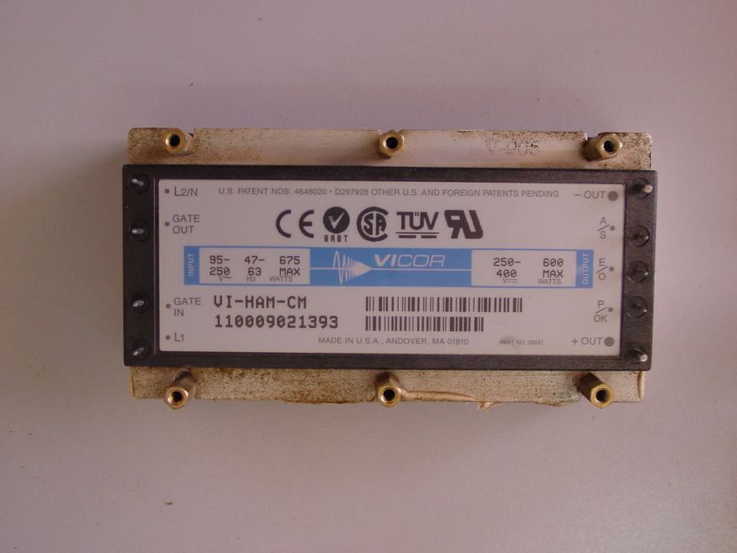
Here is a photo of the Harmonic attenuator module.
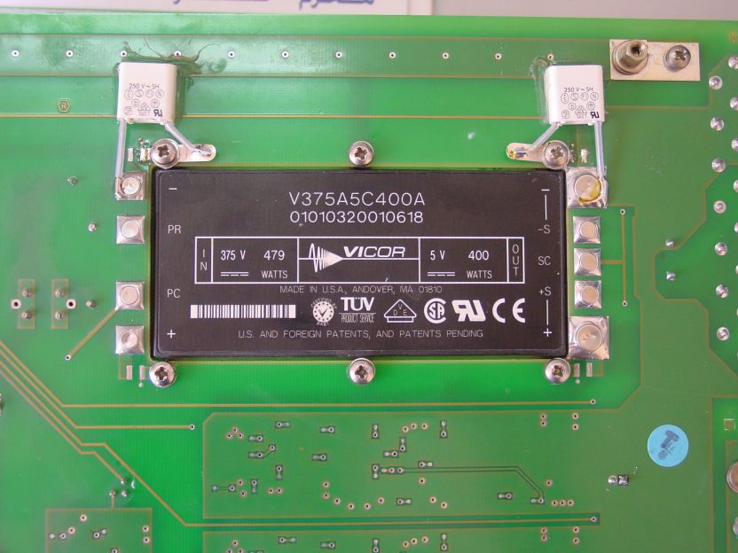
The AC-DC conversion is handled by the other module (also by Vicor):
The AC-DC conversion is handled by the other module (also by Vicor):
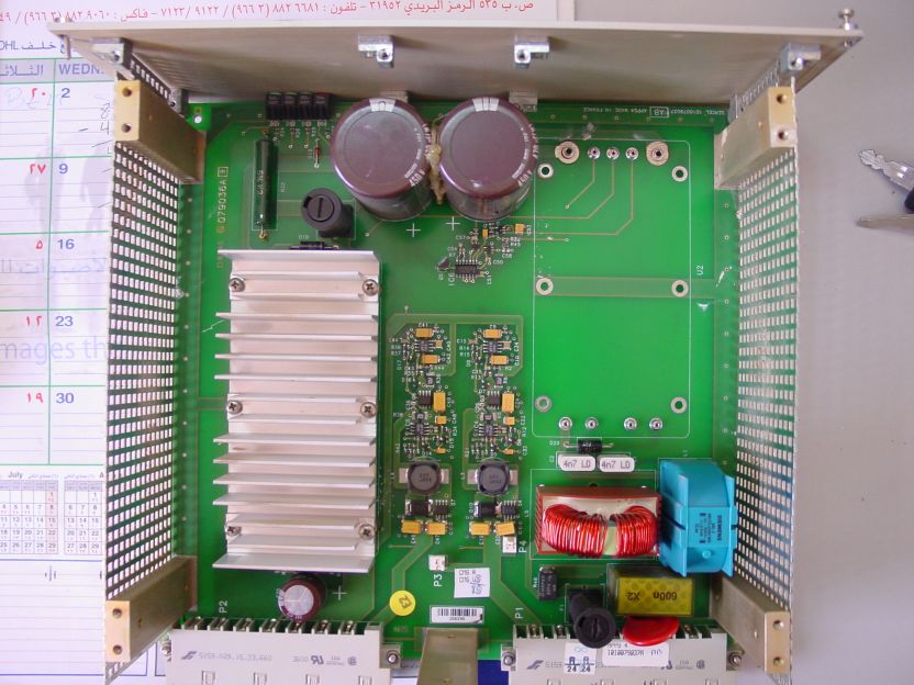
The inside of an APPS4,with one module removed (blank
area in upper right)
area in upper right)
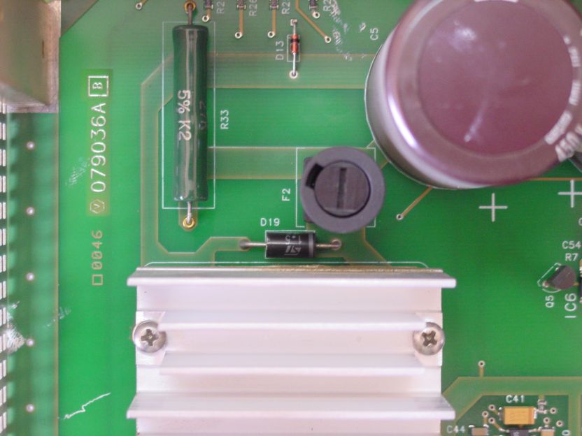
Protection
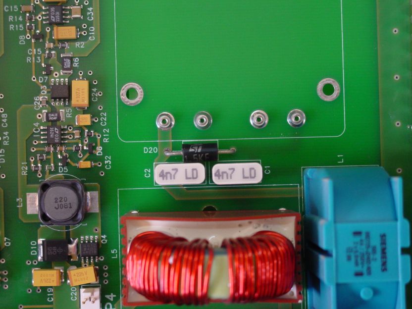
D20 is a protection system which works with Fuse F1.
It is effectively back to back zenners
The manufacturer's ref is ST 1.5KE440CA
Sercel ref 4410283
Fuse F1 is a 5A, 5x20 Fast Blow fuse
Sercel Ref 5330073
D20 is a protection system which works with Fuse F1.
It is effectively back to back zenners
The manufacturer's ref is ST 1.5KE440CA
Sercel ref 4410283
Fuse F1 is a 5A, 5x20 Fast Blow fuse
Sercel Ref 5330073
On the DC Side, a similar system is used, but the protection diode is one directional.
The Part id D19 and it works with Fuse F2
Manufacturer's ref is ST 1.5KE440A
Sercel Ref 410282
Fuse F2 is a 2A 5x20 fast Blow fuse
Sercel ref 5330211
The Part id D19 and it works with Fuse F2
Manufacturer's ref is ST 1.5KE440A
Sercel Ref 410282
Fuse F2 is a 2A 5x20 fast Blow fuse
Sercel ref 5330211
This page contains various bits of errata ascociated mostly with the 408. It is not necessarily information endorsed by Sercel.
It is in no particular order.
It is in no particular order.
SUN Station Graphics
For the Blade 1000 the graphics card is a creator 3D, PGX64 works fine too.
For Ultra 5 or Blade 100 GFX32 or PGX64
To set resolutions and modes
find the file ffbconfig (This may not be present in Blade 100 - see m64config)
to set resolution, type
ffbconfig -dev /dev/fb1 -res 1280x1024x76
to display current resolution, type
ffbconfig -prconf
To find out about the graphics cards, type
ls -l /dev/fb*
For GFX32 cards, find GFXconfig and type:
GFXconfig -i
it is in /usr/sbin
This brings up a configuration program that is a lot easier to use than the Solaris crap.
For M64 cards, use M64config in /user/sbin
This command will flash up the left screen of a multiscreen:
system if logged in as root, from command prompt log in.
/usr/openwin/bin/openwin -dev/dev/fb1 left -dev/fb
To flash up a specific screen,
/usr/openwin/bin/openwin -dev/dev/fb0
/usr/openwin/bin/openwin -dev/dev/fb1
/usr/openwin/bin/openwin -dev/dev/fb2
in /export/home/user408 there is a file : productsEnv.hci408
which contains various startup environment variables for the HCI, including the number of screens.
By default, it is hidden. Knowing about this file is very useful if you have graphic problems - IE someone enables 3 screens when the proper patches have not been loaded. In this case the system will not start properly. You can however log in to Open Windows or CDE (IE not from the command prompt login, but the graphics one) and edit the file. Then when you restart, you should be OK. Otherwise you need to reload the Sercel application software.
3 Screens on a Blade 100.
The graphic boards must be installed inthe following way :
- in slot PCI 1, the card corresponding to the 2nd screen.
- in slot PCI 3, the card corresponding to the 3rd screen.
We need to swap some PCI slots for things to work properly. From the OBP:
setenv pci-probe-list 7,c,3,8,d,13,5
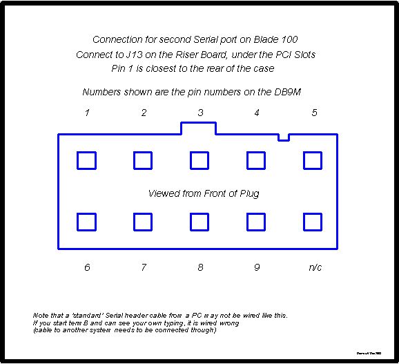
Serial Ports on Blade 100/150
Sometimes you need an extra Serial port, IE for Nav data etc. Sercel would have you purchase a serial adapter card, which is fine, but there is an easier and cheaper option.
The Blade 100 appears to only have 1 serial port, but appearances can be deceptive.
The OS recognizes TermB and it (The port) is part of the hardware.
Physically the connector is J13, located on the Riser board, below the PCI Slots.
The header socket looks like a standard one for a PC, but it is wired differently.
Adding A Zip Drive to a Blade 100
It is possible to add a ZIP drive to a Blade 100 (also to an Ultra 5, but physically there is no where to put it in an Ultra 5).
The ZIP drive replaces the Smartcard reader, which is not used anyway.
It is extraordinarily awkward to get a ZIP drive installed in a Blade 100. The power cable is just too short and the IDE2 connector on the wrong side of the board.
Be aware that there is a connector on the correct side, that looks exactly like an IDE connector, but it is a Debug connector and you cannot connect a drive to it.
The ZIP drive should be configured as a Master A drive, with 2 jumpers. There are 2 possible ways to route the cables - over the top (bad) or under the CD drive and out the slot in the centre divide (better, but still not fantastic)
If going under the CD drive, you need to remove the plastic card guide block.Only an 80-conductor cable will fit through the slot, a normal one is too big.
You will also need an extension for the power cable.
Once installed, it appears in File Manager under the Root as rmdisk.
IE after starting File Manager, go to the root and then rmdisk.
PLCI Boards
These are little known, hidden boards in the back of the chassis. they provide power for the Aux FDUs. One is required per LCI board, hence 5 for XL, 1 for UL.
They are located behind backplane and are aprox 4"x2" and plug in.
They are interchangeable.
Therefore if have problems with AUX or line after swapping LCIs think about these.
Timestamps
Time stamps are generated on the first LMP board of the CM.
It corresponds to T0 or TB or start of acquisition depending on terminology
When a TB is received by the LMP, it memorizes the time and places it in the LMP header. The same time is written to tape later.
The clock used to produce the time stamp is therefore the CM clock, which is synchronized to the HCI clock when the user clicks Online.
Blocked and Unblocked Tape Formats
A Data File recorded on tape is divided into sections. Each section is separated by an Inter-Block-Gap (or IBG) which is a special code recognized by the drive.
This system is much like the sectoring system used on disk drives. The difference is that in disk drives, the sector size is fixed, whereas on tape, the block sizes can be variable.
There are limits to the size of blocks that can be recorded on tape.
These limits come from the recording system and also from the size of the drive's buffer memory. In our case with the SN408 recording system and M8100 drives, the maximum block size is 128KB for the UL and 265KB for the XL.
In a conventional (Unblocked) SEG-D file, we write our File header followed by an IBG, then a full trace (with Trace header) followed by an IBG and then the next trace followed by an IBG and so on until the last trace is written.
See how several (probably around 10 or 12) traces are written together with only one IBG.
The down side of this of course is that the processing system needs to be able to take care of it and if there is an error within a block, several traces are lost, not just one as in Unblocked Mode. If the processing center can handle this then they too can save time in reading data.
With less than 4000 traces, we generally have no need to record in blocked mode, as the drives can keep up with the recording system. If we went to a shorter sweep or more channels though, this may not be the case and Blocked mode might have to be considered.
A few more details and diagrams are available in the Sercel documentation -
408user2.pdf page 15. Diagrams above were extracted from here.
Note that each trace is separated by an IBG.
In Blocked Mode recording, we write the file header followed by an IBG as usual then we group traces together up to the maximum size allowed by the system (128KB for UL, 256KB for XL) and write them in one go, followed by an IBG. Then we write the next set of traces followed by an IBG, until all traces are written.
This allows us to match the drive's buffer size with the recording systems write capabilities and it results in much faster recording - up to 30% faster in some cases.

